揭开面纱
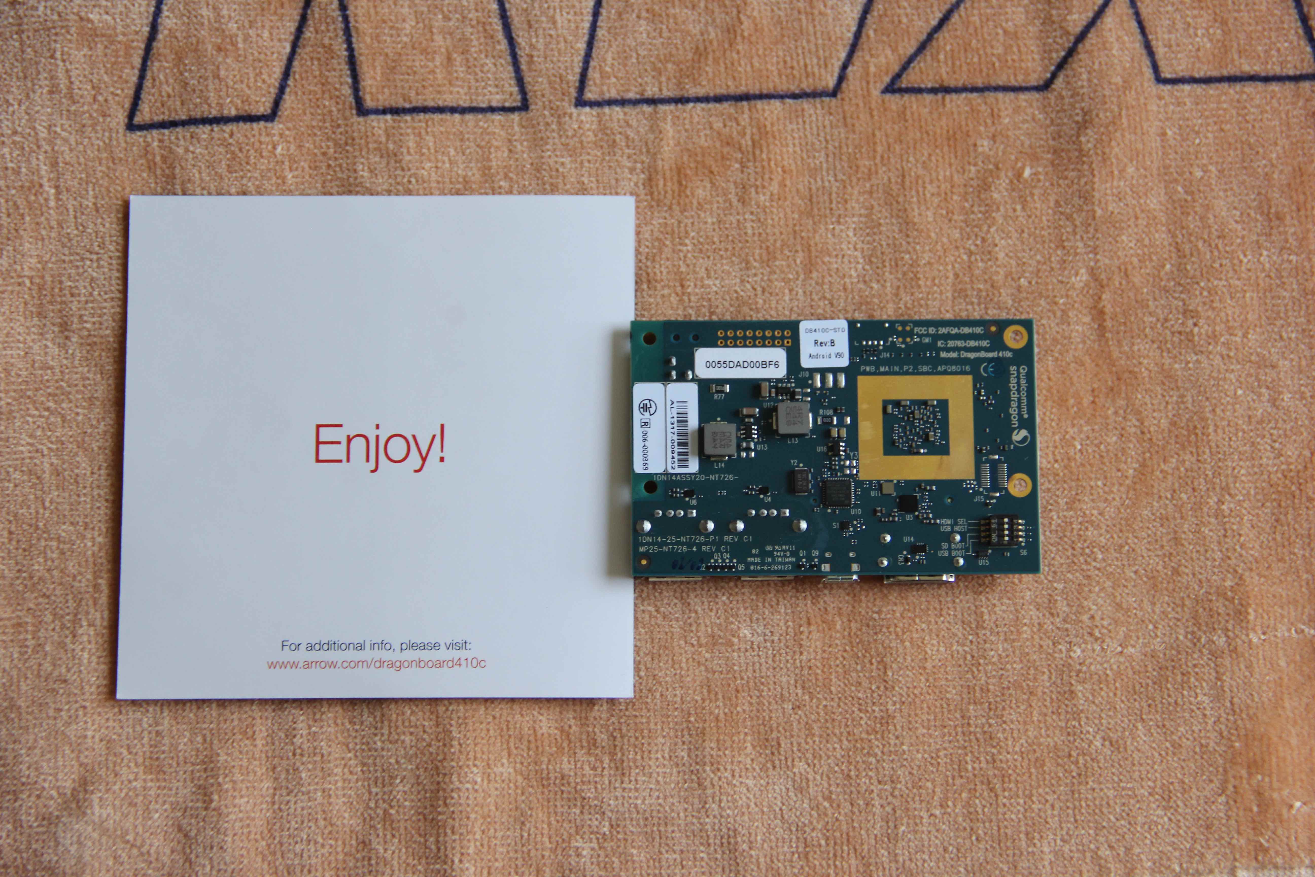
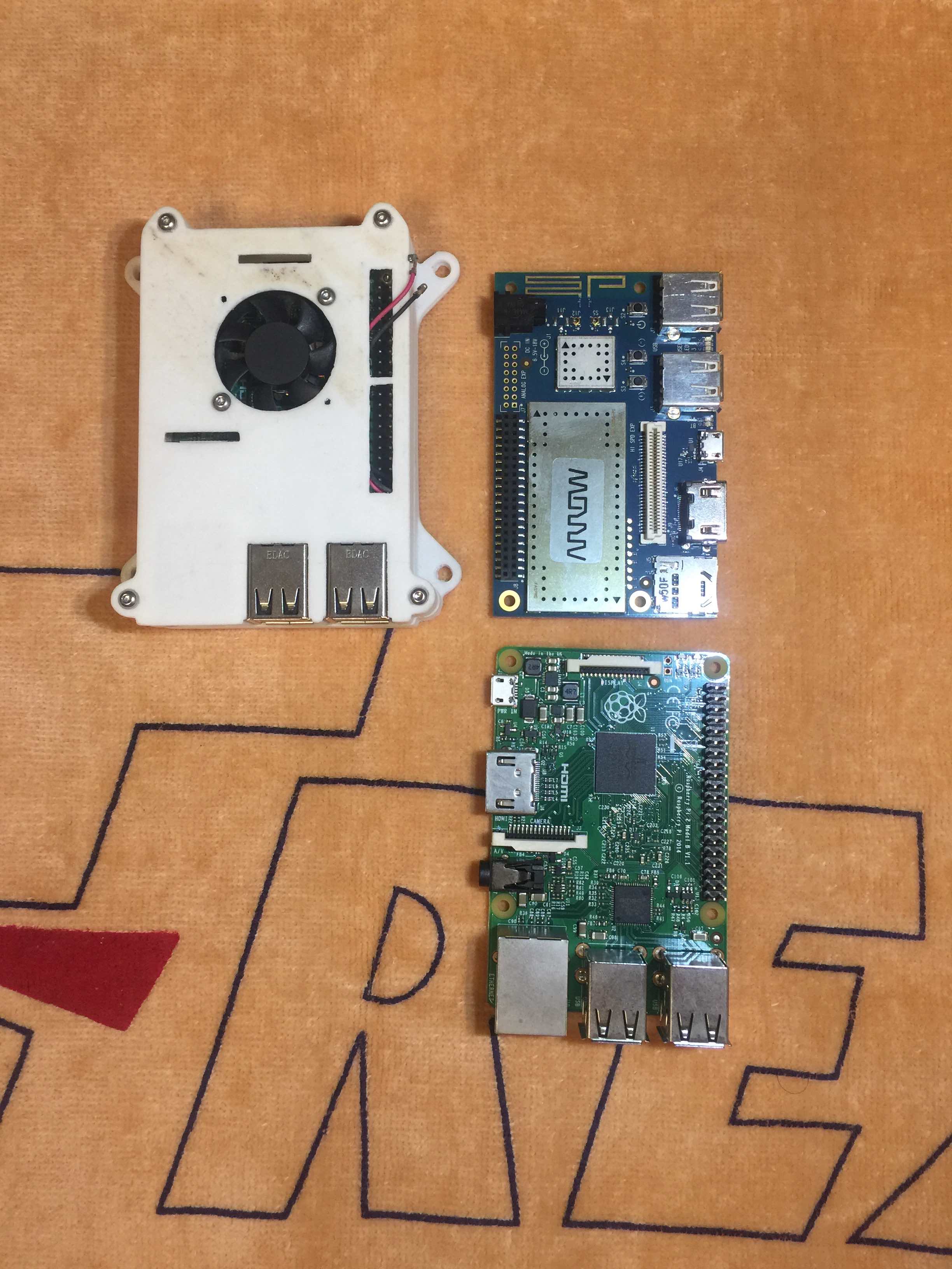
机缘巧合的情况下,博主有幸得到了一次高通Dragonboard410C开发板的试用机会,Dragonboard410C也熟称龙板,下面简单介绍一下这个板子吧,资料摘录于网上。
硬件方面,DragonBoard 410c是一款搭载Qualcomm® Snapdragon™ 410(64位的四核处理器)的开发板,内置 8GB eMMC (支持标准microSD卡槽),内置wifi、蓝牙、和GPS模块,具有HDMI 输出及USB 接口 (3个),兼容96Boards消费版(CE)规范。
软件方面,DragonBoard 410c目前已经可以运行Android5.1、Ubuntu、Windows 10 IoT Core、Debian系统。
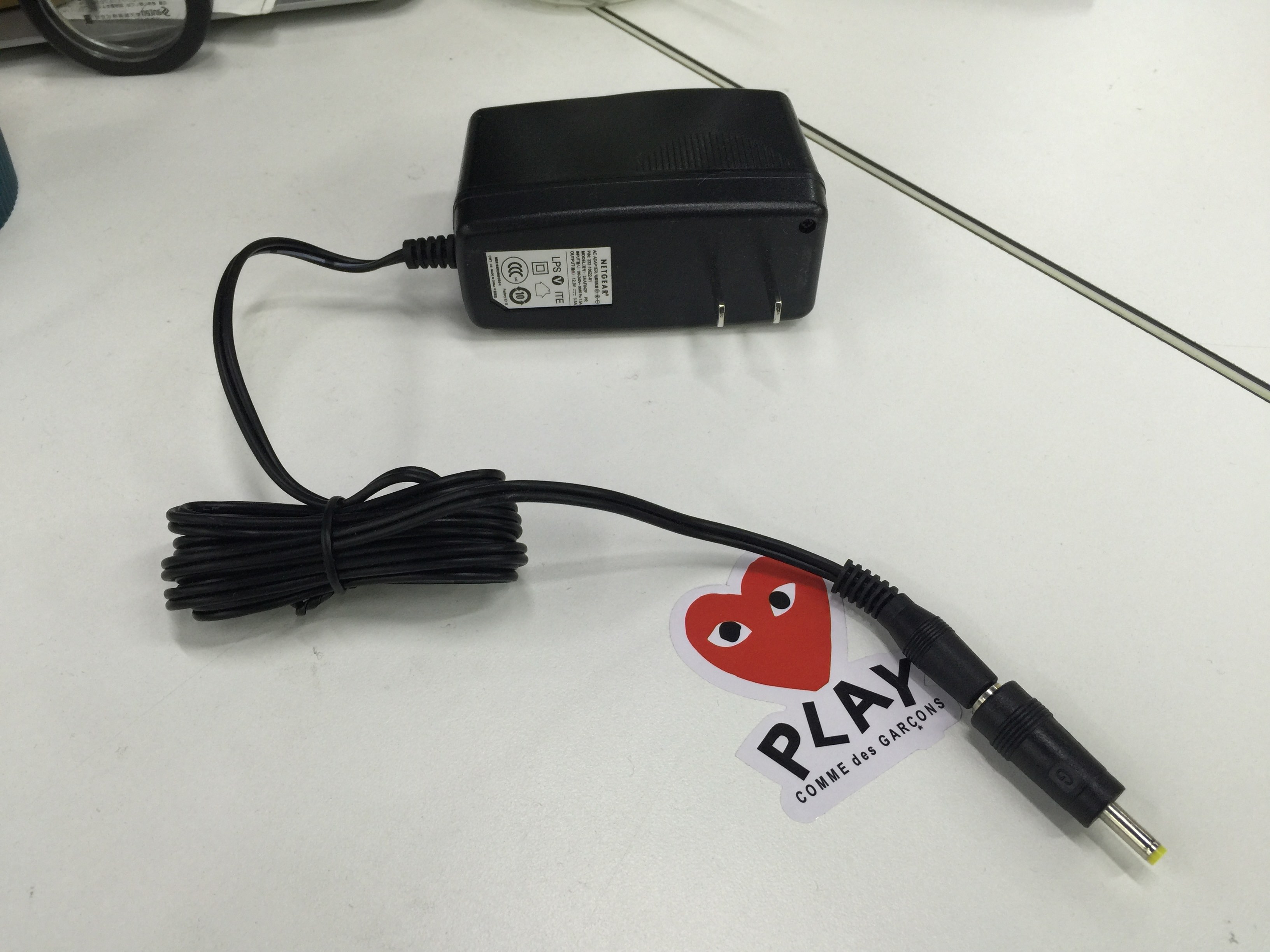
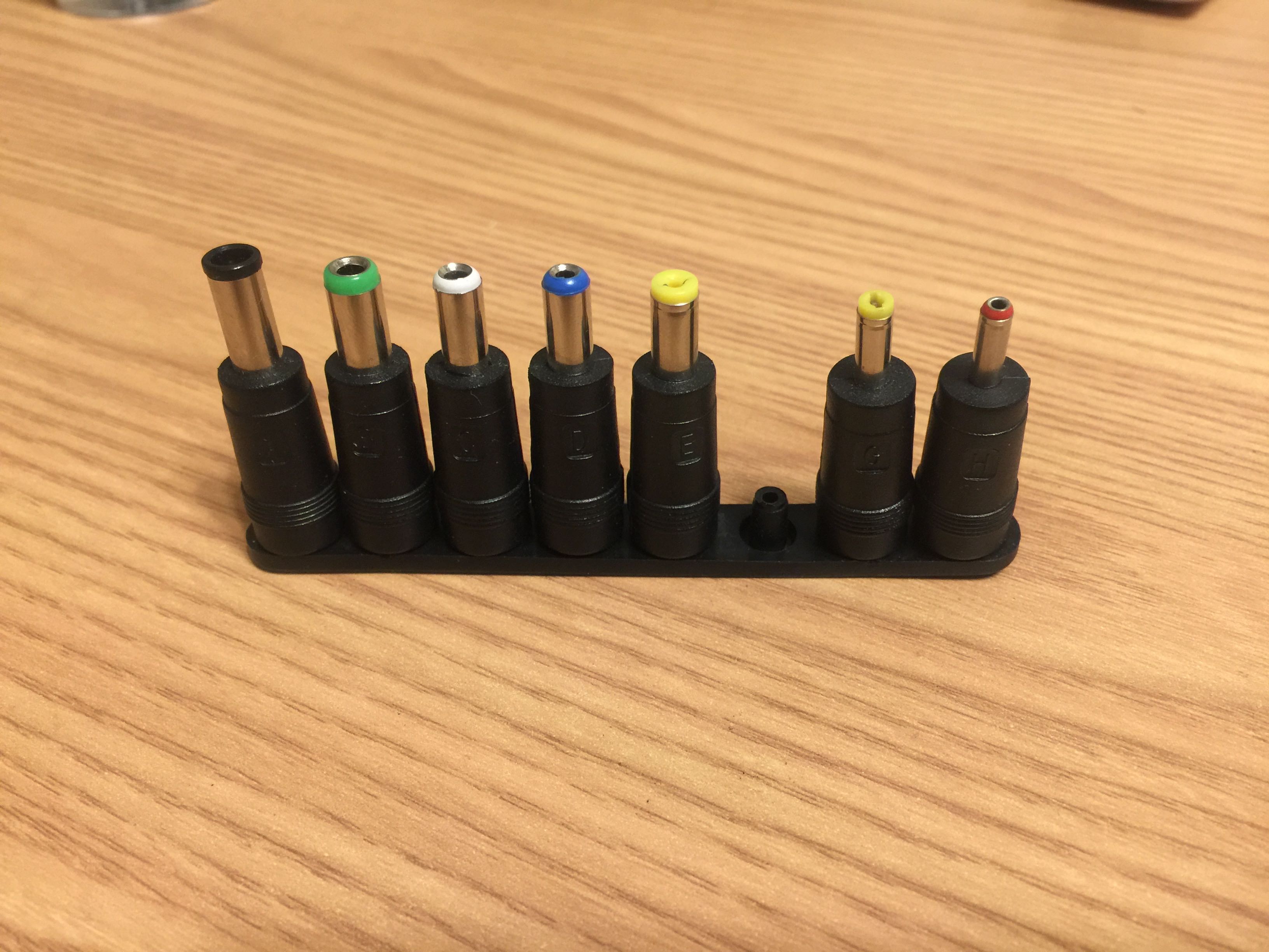
经过一段时间的等待,开发板送到博主手里,博主便面临了第一个问题,以往树莓派或者国产Pi这类开发板都是USB供电,但是龙板需要12V 2A的电源进行供电,而且电源插头还比较小,经过淘宝筛选,最终选定如下电源组合方案:网件路由器原装电源 + 万能DC转接头。东西到手后发现非常好用。
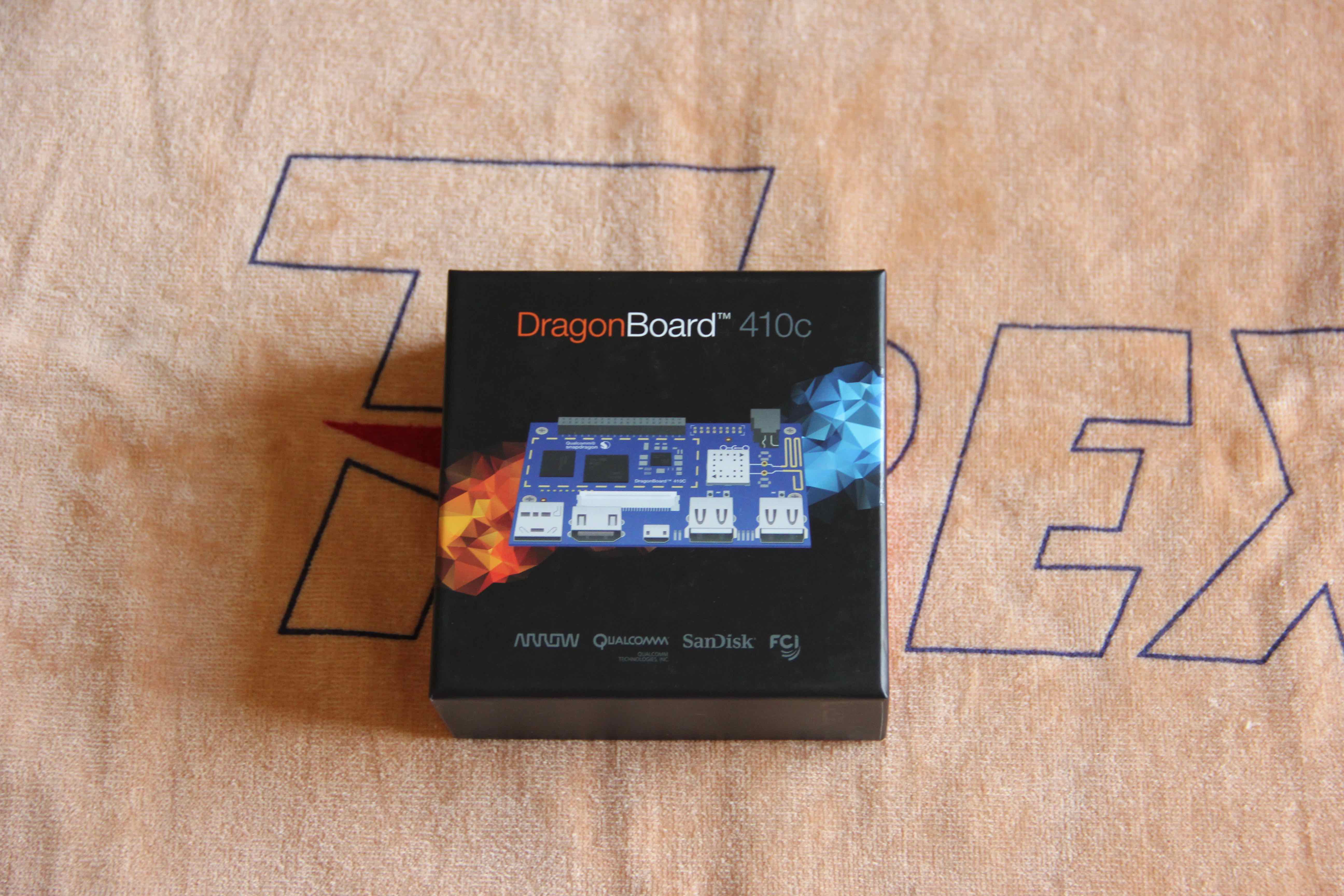
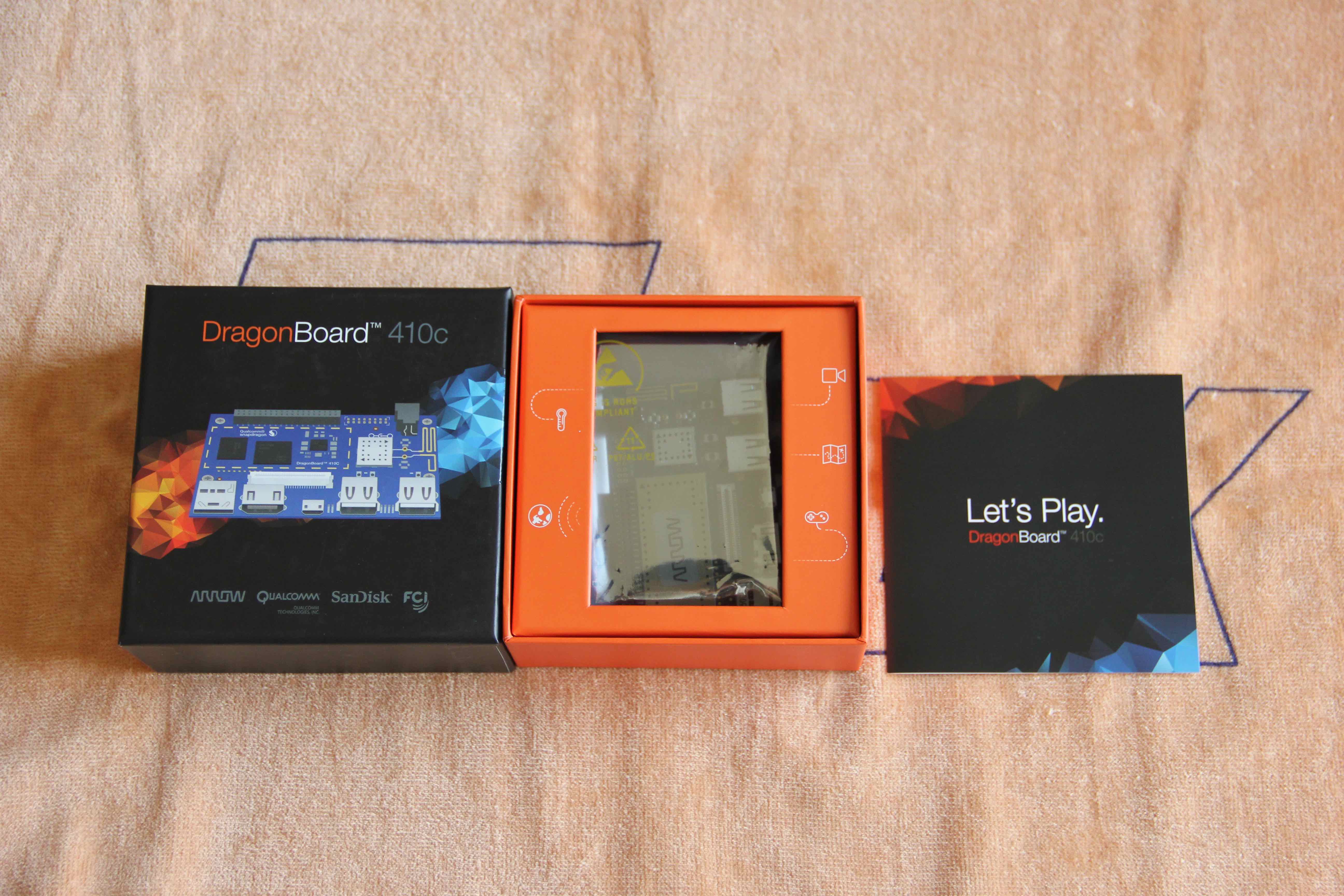
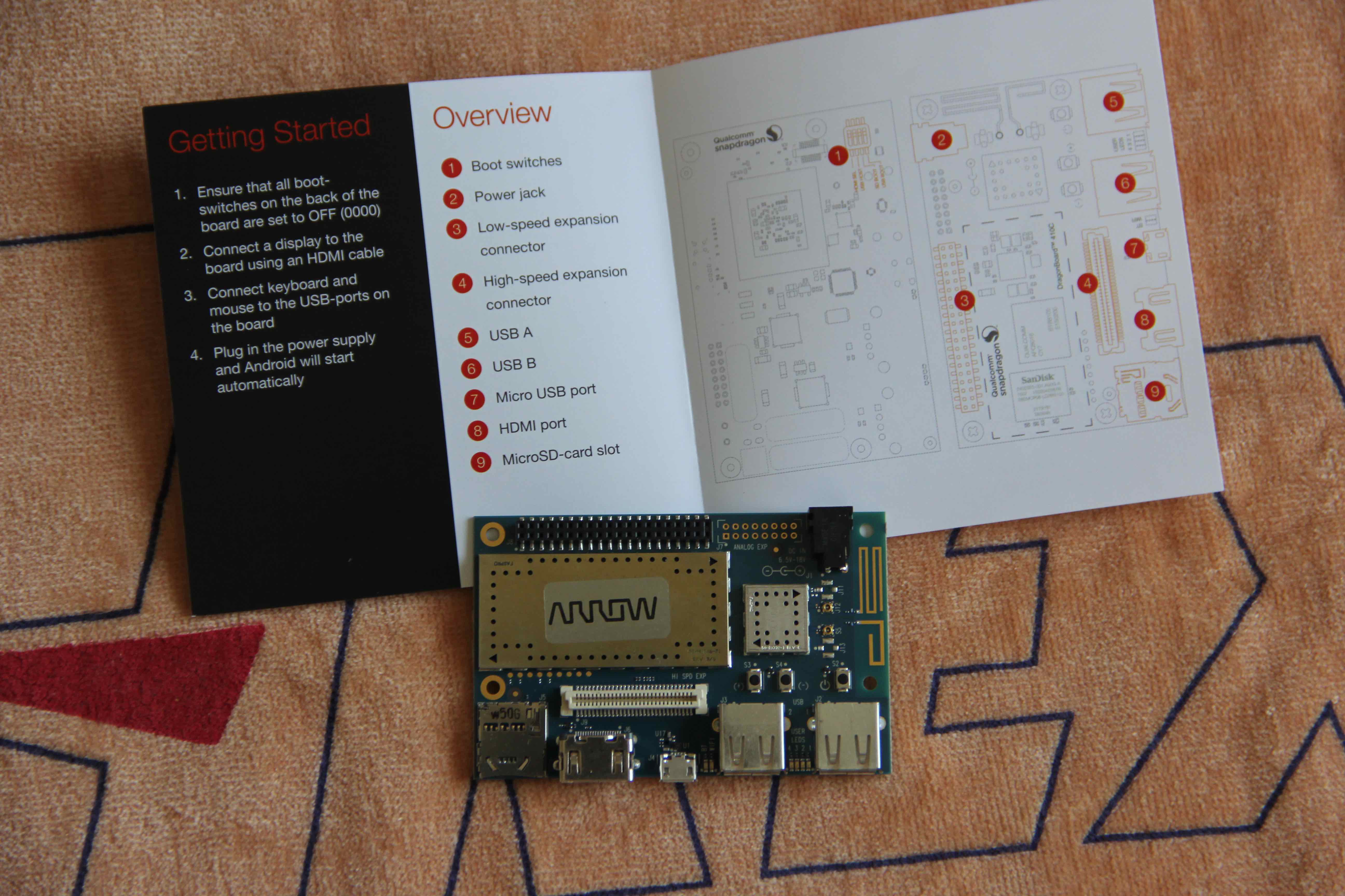
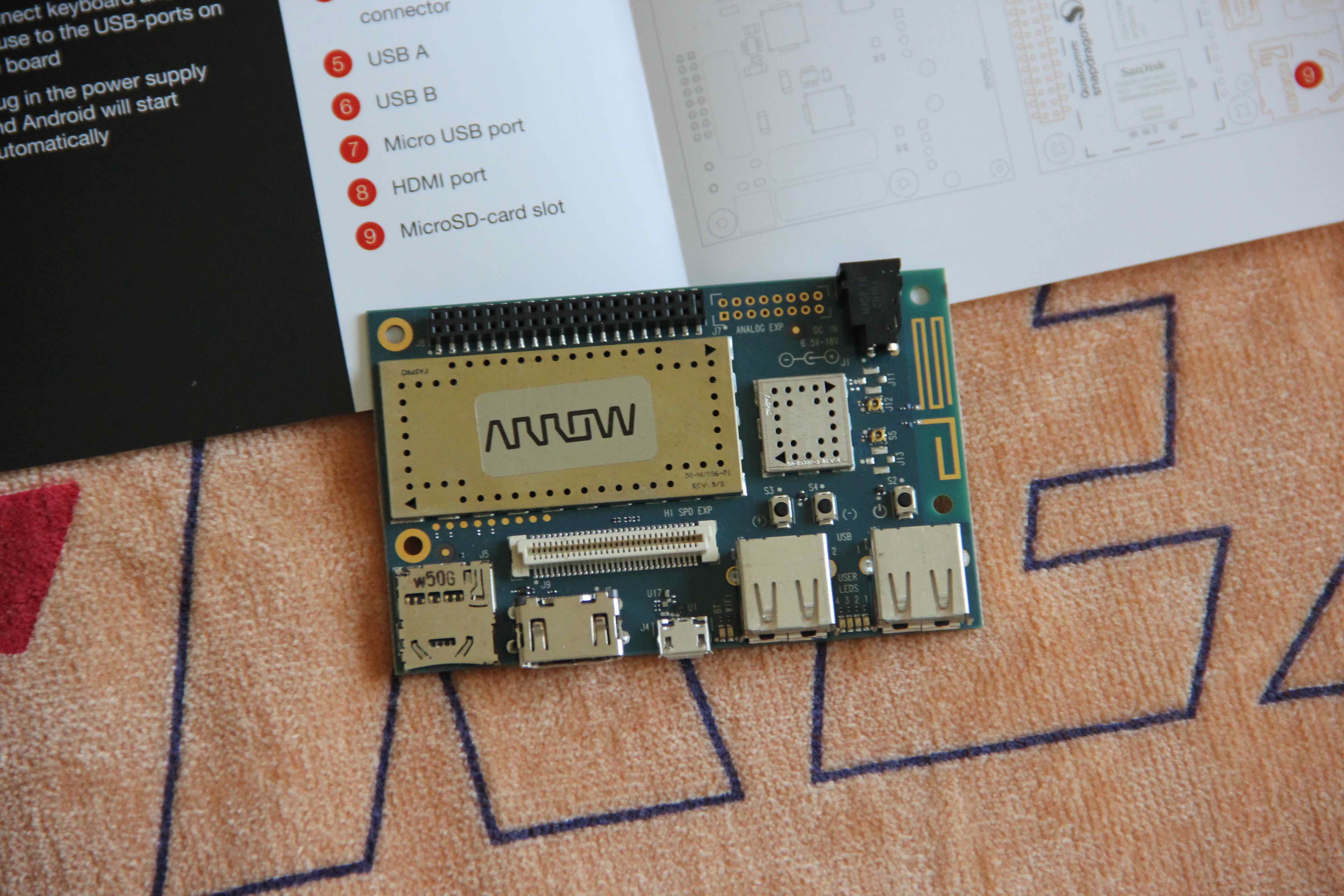
装系统
龙板装系统还是比较简单的,博主选用Debian系统,装新系统前使用了一会默认自带的Android,正好接到电视上,运行十分的流程,毫无卡顿的感觉。
1.TF卡安装
Mac终端登录到root用户
diskutil unmount /dev/disk1s1
dd bs=409600 if=debian.img | pv | dd bs=409600 of=/dev/rdisk1
这里加pv命令是为了能看见写入进度
当TF卡烧录完成之后,龙板断电,把TF卡插入龙板,将开发板背面的启动选择开关拨动为0-1-0-0,即将SD Boot拨动到ON位置,其他关闭,之后连接显示器、鼠标、键盘等外设,龙板上电开机,按照图形提示安装即可,步骤很少比较简单。
2.Fastboot线刷
博主是iOS程序猿,一些Android程序猿电脑估计Fastboot是必备的,博主这里现安装的
下载Google官方的Fastboot独立包:
platform-tools-latest-darwin.zip
platform-tools-latest-linux.zip
platform-tools-latest-windows.zip
之后解压缩到工作目录,并在终端里导入环境变量
export PATH=$PATH:工作目录/platform-tools
龙板Fastboot连接
首先需要确保开发板背面的启动选择开关处于0-0-0-0状态,然后需要通过usb连接到电脑。先启动时按住S4(音量 -)键再插电源,20左右fastboot devices看见设备。之后烧写bootloader、boot、root
顺便利用nBench来横向测评一下龙板、树莓派3、树莓派2的性能横向对比
龙板:
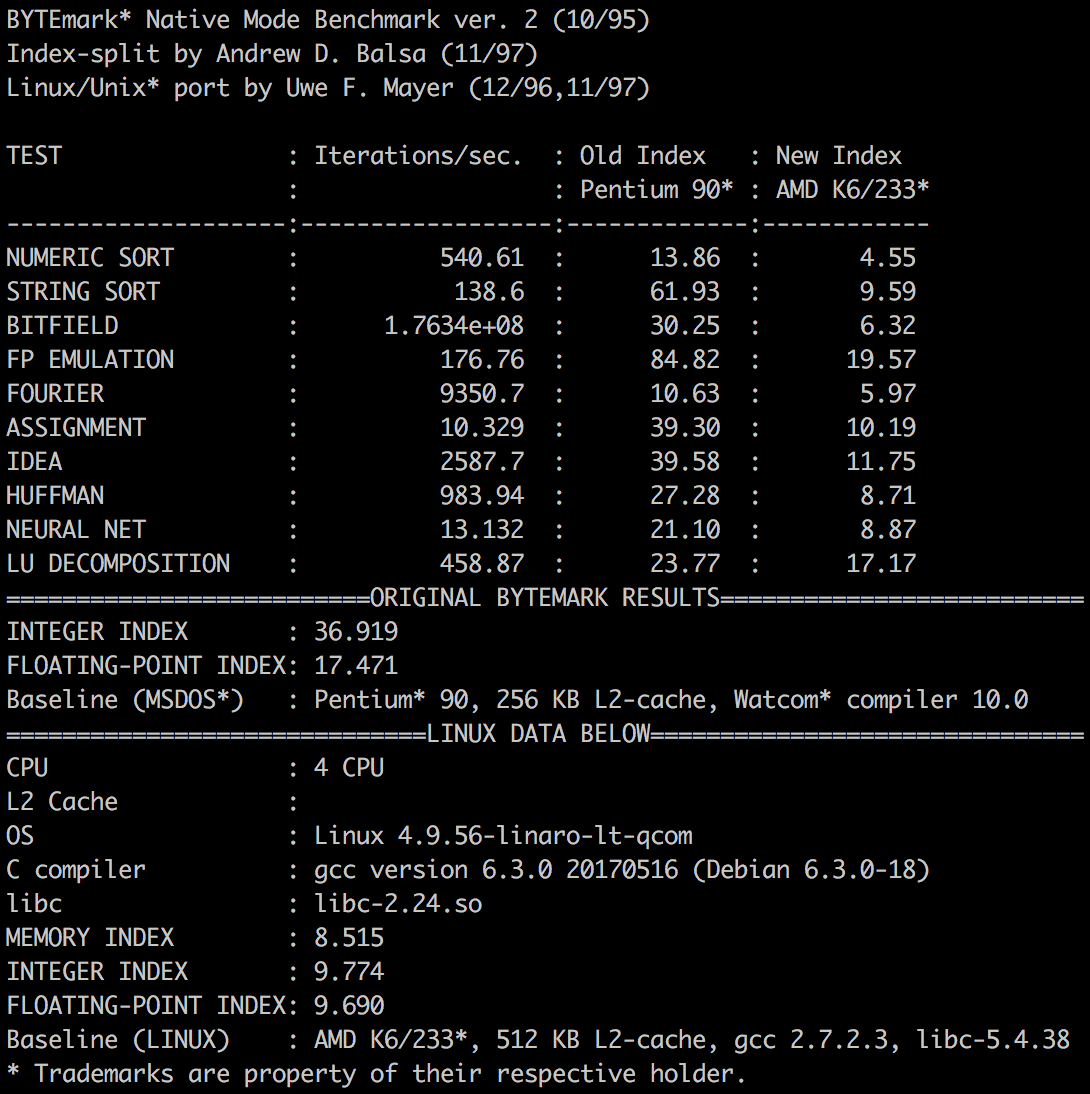
树莓派3:

树莓派2:

试用选题
起初博主是打算把之前做的机器人核心板用这个龙板来实现的,但是后来考虑时间很短,虽然三周,但是帝都的程序员加班大家懂的,难免保证不了开发时间,所以再三考虑,决定把选题修改为环境监测器,模拟要解决的情景就是上班族在下班回家的路上就可以通过手机查看家里的温湿度情况,然后控制空调,来预先调节好家里舒适的温度环境。
功能设计
针对上述情景,其实博主想做的就是一个最简单的闭环操作,检测到传感器检测到温湿度->反馈给开发板->开发板通过手机反馈给人->人操作空调调整温湿度->形成闭环。那么就设计功能如下
1.外网服务器,跑内网穿透服务端用;
2.开发板需实现温湿度采集,和控制空调,以及搭建Web服务器和运行内网穿透客户端;
3.后端服务接口,提供历史温湿度、实时温湿度;
4.iOS客户端,用来查看温湿度和控制空调;
查找资料
1.内网穿透之前就一直在用,这个就不过多说明了,Ngork和FRP都可以,博主选用的是FRP,服务于家里的Gen8塔式服务器和几个树莓派。
2.温湿度采集需要用到DHT11模块,之前这类模块可以很简单方便的在树莓派上使用因为有现成的驱动和程序,在龙板上需要自己写驱动,DHT11使用GPIO通信,故需要查找龙板的GPIO操作方法,以及Linux系统下与驱动相关的知识(设备树、内核编译等)。
3.遥控空调使用的是Linux下开源的LIRC软件,这是一个红外万能遥控器程序,需要与红外发射模块和红外接收模块配合使用,但是有一个困难跟上一条一样,就是树莓派内置了LIRC的设备驱动lirc_rpi,龙板上没有,也得自己想办法编写驱动。
到这里博主其实遇见了很多困难和问题,最主要的一点客观原因是,博主本质职iOS程序猿,接触硬件是兴趣因素比如我喜欢鼓捣玩或者做做机器人玩玩模型啥的,另一点接触硬件的原因就是第一份全职工作是开发智能家居,所以综上,博主属于那种软件程序猿,但是硬件懂一些懂的不特别深入的那种,这时候查阅高通文档的时候就遇见了一些困难,比如操作GPIO需要了解设备手册和原理图一类的,有时候搜索查阅文档就显得有些力不从心。
开发环境的搭建
这里博主在Gen8上虚拟化了一个Ubuntu来做编译内核和驱动用,之后再传到龙板上,因为毕竟服务器的编译速度和磁盘空间大很多。
下载内核源码,内核源码仓库地址:
kernel.git
使用Tag:debian-qcom-dragonboard410c-17.09
可以用git克隆下来自己检出代码,也可以直接下载源码压缩包
kernel-debian-qcom-dragonboard410c-17.09.tar.gz
下载编译工具:
gcc-linaro-6.3.1-2017.02-x86_64_aarch64-linux-gnu.tar.xz(这里博主机器上用的是老版本的)
下载DTC(设备树编译工具):
sudo apt-get install device-tree-compiler
git clone git://codeaurora.org/quic/kernel/skales
下载initrd镜像
打开http://builds.96boards.org/releases/dragonboard410c/linaro/debian/latest/
下载:initrd.img-4.9.56-linaro-lt-qcom
至此下载准备工作完成,把文件按照分类放到工作目录的根目录下,分别是gcc-linaro-4.8-2015.06-x86_64_aarch64-linux-gnu(编译工具)、image(镜像)、kernel-debian-qcom-dragonboard410c-17.09(内核源码)、skales(设备树编译工具)

工作目录如上
配置编译源码时编译工具的环境变量,有2种方法:
1.直接修改内核源码的Makefile,修改ARCH和CROSS_COMPILE
ARCH ?= arm64
CROSS_COMPILE ?= /root/db410c/gcc-linaro-4.8-2015.06-x86_64_aarch64-linux-gnu/bin/aarch64-linux-gnu-
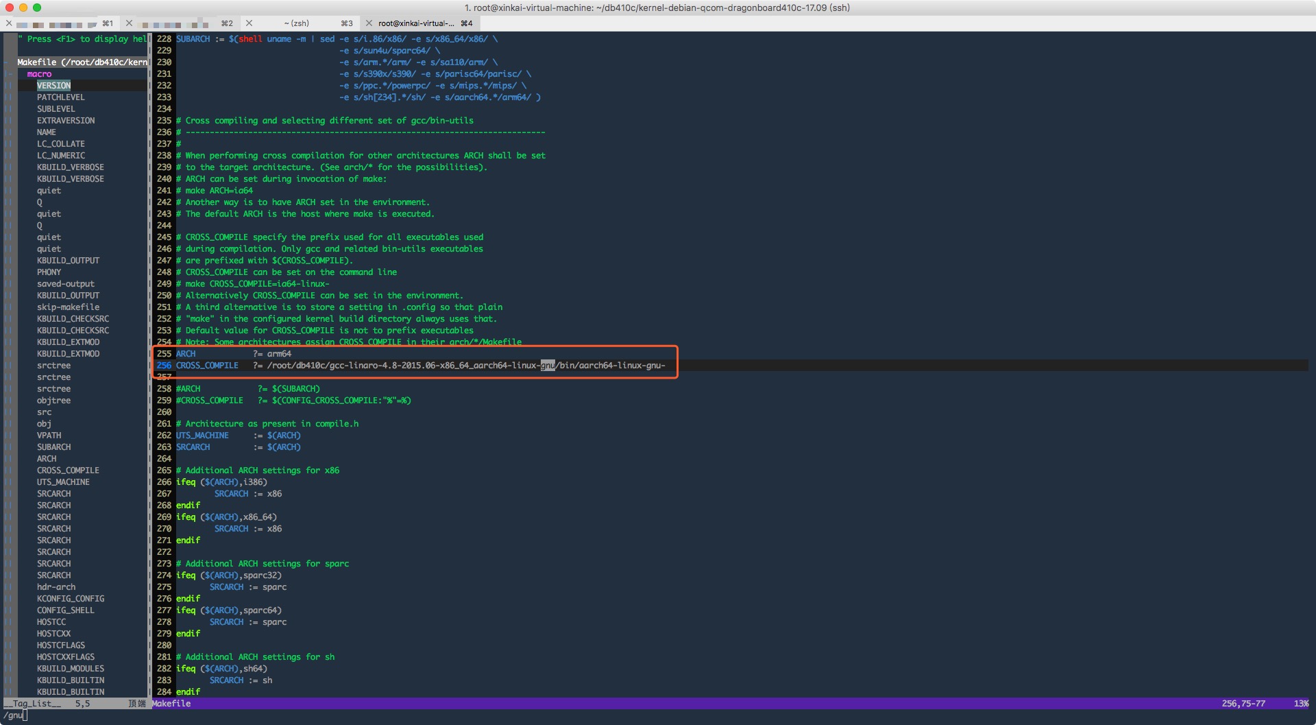
2.Makefile里写默认是环境变量,所以可以每次ssh登录到终端后,export环境变量,当然,想写死在环境变量的配置文件里也是可以的
export ARCH=arm64
export CROSS_COMPILE=/root/db410c/gcc-linaro-4.8-2015.06-x86_64_aarch64-linux-gnu/bin/aarch64-linux-gnu-
至此,开发环境准备完成
开发
看了博主说那么多应该也能感觉到,博主是好折腾的那种人,软件、硬件、服务器、服务端、运维全都接触,所以上来就先在自己的Git上创建了该试用项目的组织,并邀请好友一起帮忙开发(PS.一个人时间太紧了,总加班,ಥ_ಥ)~
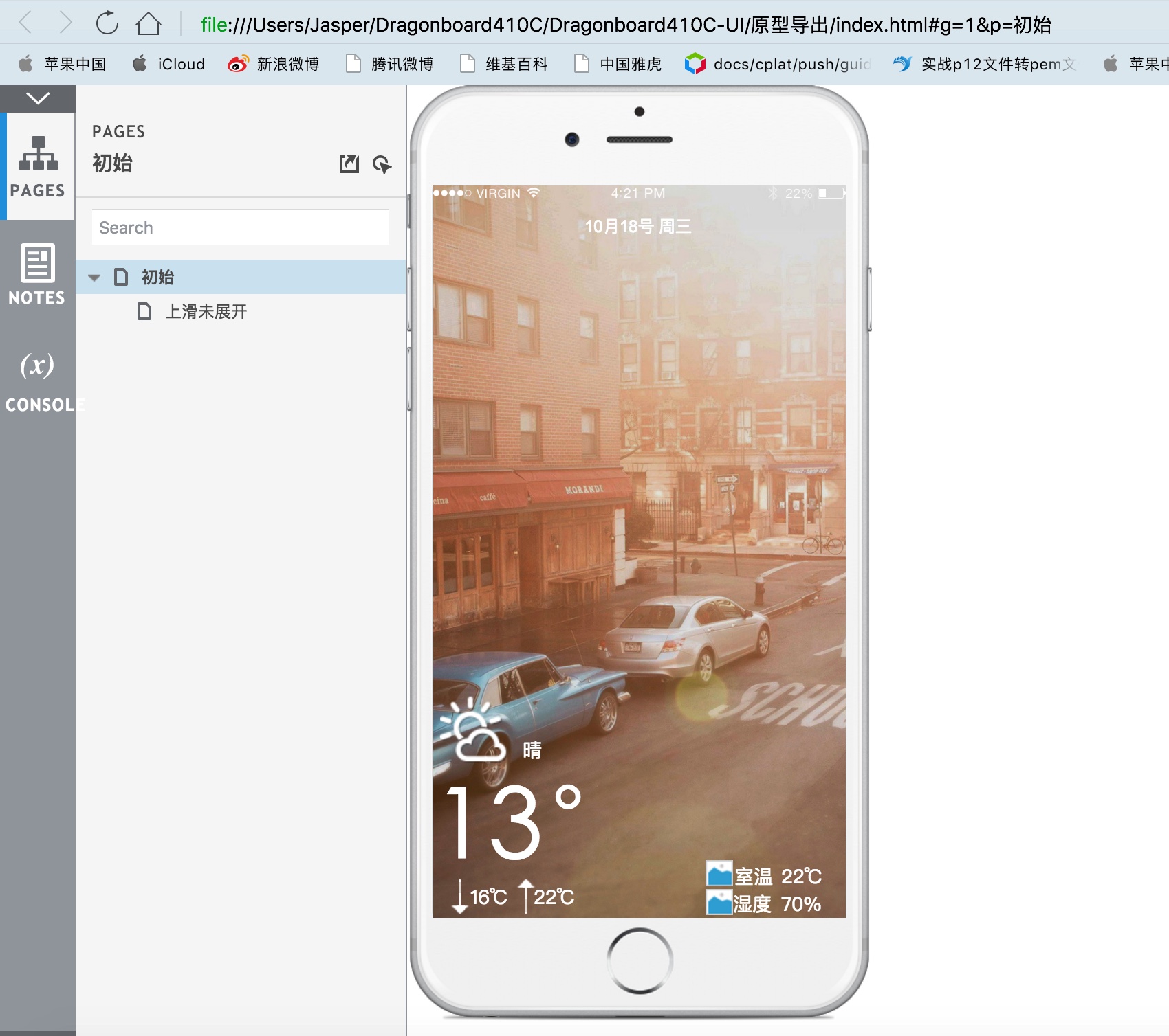
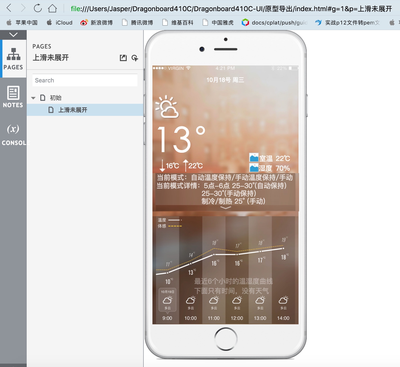
花了两天晚上的业余时间,参考了一款天气预报的APP,画出了原型图
内网穿透
使用FRP,穿透的方案是:公网Nginx(域名解析)->公网FRP服务端->龙板FRP客户端->龙板Nginx(域名解析)。
创建工作路径mkdir -p /etc/frp
分别把frpc frpc.ini放到工作路径下
|
1 2 3 4 5 6 7 8 9 10 11 12 13 14 15 16 17 18 19 20 21 22 23 24 |
[common] server_addr = zasper.net server_port = xxxx log_file = ./frpc.log log_level = info log_max_days = 3 privilege_token = xxxx pool_count = 5 tcp_mux = true user = Dragonboard410C login_fail_exit = true protocol = tcp [ssh] type = tcp local_ip = 127.0.0.1 local_port = 22 use_encryption = true use_compression = true remote_port = xxxx [web] type = http local_ip = 127.0.0.1 local_port = 80 custom_domains = xxxx.zasper.net |
安装supervisor做FRP的守护进程
sudo apt-get install supervisor
编写服务的conf
sudo vim /etc/supervisor/conf.d/frpc.conf
启动supervisor
supervisord -c /etc/supervisor/supervisord.conf
|
1 2 3 4 5 6 7 8 9 10 11 12 13 |
[program:frp] user=root command=/etc/frp/frpc -c /etc/frp/frpc.ini startsecs=1 startretries=100 autorstart=true autorestart=true stderr_logfile=/tmp/err-frps.log stderr_logfile_maxbytes=50MB stderr_logfile_backups=10 stdout_logfile=/tmp/out-frps.log stdout_logfile_maxbytes=50MB stdout_logfile_backups=10 |
接下来是恼人的驱动开发了,网上Google搜索DragonBoard410C GPIO的关键词,搜出来的全是如下
1. 导出
/sys/class/gpio# echo 44 > export
2. 设置方向
/sys/class/gpio/gpio44# echo out > direction
3. 查看方向
/sys/class/gpio/gpio44# cat direction
4. 设置输出
/sys/class/gpio/gpio44# echo 1 > value
5. 查看输出值
/sys/class/gpio/gpio44# cat value
6. 取消导出
/sys/class/gpio# echo 44 > unexport
但是后来发现驱动里一般不用这个方法,于是静下心来开始查阅学习了Linux ARM板的驱动开发流程。
DHT11
先改写设备树增加设备描述,之后编译内核、设备树,并与initrd一起生成boot.img引导镜像。
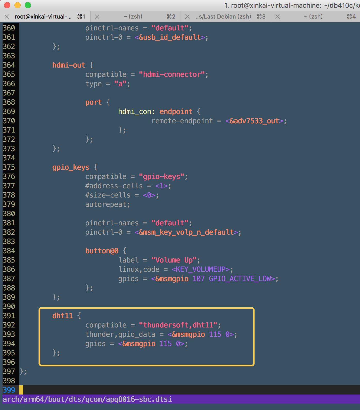
添加设备树在跟节点上
之后配置编译
make defconfig distro.config
make -j4 Image.gz dtbs KERNELRELEASE=4.9.56-linaro-lt-qcom
把编译好的设备树生成镜像
./skales/dtbTool -o image/dt.img -s 2048 kernel-debian-qcom-dragonboard410c-17.09/arch/arm64/boot/dts/qcom/
把内核镜像和设备树镜像和初始化磁盘镜像,打包生成boot镜像
./skales/mkbootimg –kernel kernel-debian-qcom-dragonboard410c-17.09/arch/arm64/boot/Image –ramdisk image/initrd.img-4.9.56-linaro-lt-qcom –output image/boot-db410c.img –dt image/dt.img –pagesize 2048 –base 0x80000000 –cmdline “root=/dev/disk/by-partlabel/rootfs rw rootwait console=ttyMSM0,115200n8”
之后龙板开启到fastboot模式,刷入boot镜像,系统镜像不需要重刷。
刷好后重启进入系统,这里的感受就是,龙板每次重启速度真的很快。重启后进入/sys/devices/platform/路径下,如果有dht11路径,则说明设备树添加成功,进入DHT11路径后发现没有iio设备,这是因为我们还没有挂载驱动的原因。
这里使用github搜到的dht11.c驱动为蓝本,更改驱动的匹配标识跟设备树的一致,调整gpio获取方式,调整数据原始数据的读取。
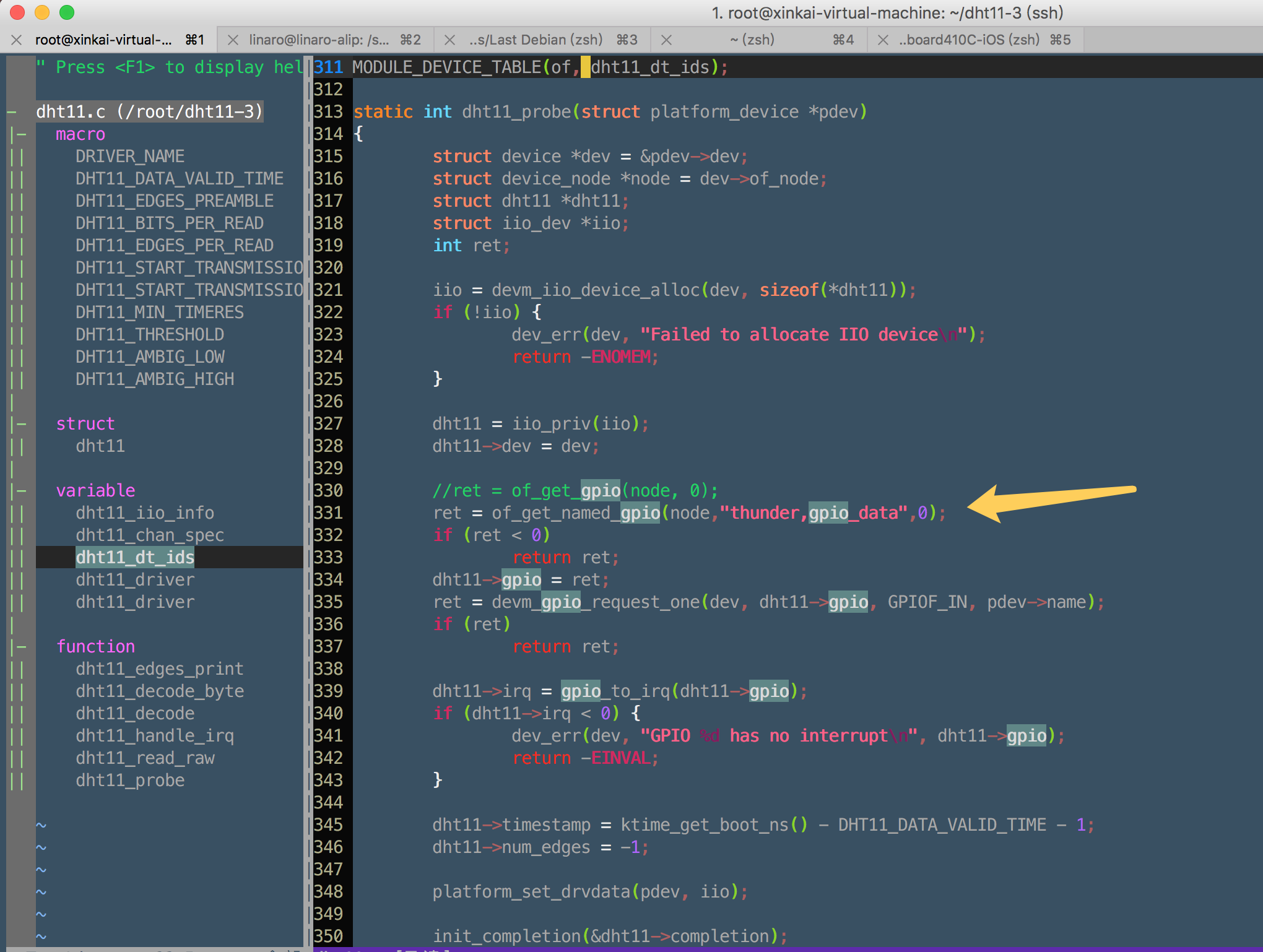
中间多次尝试多次失败的过程就不在累述,直接贴驱动源码
|
1 2 3 4 5 6 7 8 9 10 11 12 13 14 15 16 17 18 19 20 21 22 23 24 25 26 27 28 29 30 31 32 33 34 35 36 37 38 39 40 41 42 43 44 45 46 47 48 49 50 51 52 53 54 55 56 57 58 59 60 61 62 63 64 65 66 67 68 69 70 71 72 73 74 75 76 77 78 79 80 81 82 83 84 85 86 87 88 89 90 91 92 93 94 95 96 97 98 99 100 101 102 103 104 105 106 107 108 109 110 111 112 113 114 115 116 117 118 119 120 121 122 123 124 125 126 127 128 129 130 131 132 133 134 135 136 137 138 139 140 141 142 143 144 145 146 147 148 149 150 151 152 153 154 155 156 157 158 159 160 161 162 163 164 165 166 167 168 169 170 171 172 173 174 175 176 177 178 179 180 181 182 183 184 185 186 187 188 189 190 191 192 193 194 195 196 197 198 199 200 201 202 203 204 205 206 207 208 209 210 211 212 213 214 215 216 217 218 219 220 221 222 223 224 225 226 227 228 229 230 231 232 233 234 235 236 237 238 239 240 241 242 243 244 245 246 247 248 249 250 251 252 253 254 255 256 257 258 259 260 261 262 263 264 265 266 267 268 269 270 271 272 273 274 275 276 277 278 279 280 281 282 283 284 285 286 287 288 289 290 291 292 293 294 295 296 297 298 299 300 301 302 303 304 305 306 307 308 309 310 311 312 313 314 315 316 317 318 319 320 321 322 323 324 325 326 327 328 329 330 331 332 333 334 335 336 337 338 339 340 341 342 343 344 345 346 347 348 349 350 351 352 353 354 355 356 357 358 359 360 361 362 363 364 365 366 367 368 369 370 371 372 373 374 |
/* * DHT11/DHT22 bit banging GPIO driver * * Copyright (c) Harald Geyer <harald@ccbib.org> * * This program is free software; you can redistribute it and/or modify * it under the terms of the GNU General Public License as published by * the Free Software Foundation; either version 2 of the License, or * (at your option) any later version. * * This program is distributed in the hope that it will be useful, * but WITHOUT ANY WARRANTY; without even the implied warranty of * MERCHANTABILITY or FITNESS FOR A PARTICULAR PURPOSE. See the * GNU General Public License for more details. */ #include <linux/err.h> #include <linux/interrupt.h> #include <linux/device.h> #include <linux/kernel.h> #include <linux/printk.h> #include <linux/slab.h> #include <linux/of.h> #include <linux/of_device.h> #include <linux/sysfs.h> #include <linux/io.h> #include <linux/module.h> #include <linux/platform_device.h> #include <linux/wait.h> #include <linux/bitops.h> #include <linux/completion.h> #include <linux/mutex.h> #include <linux/delay.h> #include <linux/gpio.h> #include <linux/of_gpio.h> #include <linux/timekeeping.h> #include <linux/iio/iio.h> #define DRIVER_NAME "dht11" #define DHT11_DATA_VALID_TIME 2000000000 /* 2s in ns */ #define DHT11_EDGES_PREAMBLE 2 #define DHT11_BITS_PER_READ 40 /* * Note that when reading the sensor actually 84 edges are detected, but * since the last edge is not significant, we only store 83: */ #define DHT11_EDGES_PER_READ (2 * DHT11_BITS_PER_READ + \ DHT11_EDGES_PREAMBLE + 1) /* * Data transmission timing: * Data bits are encoded as pulse length (high time) on the data line. * 0-bit: 22-30uS -- typically 26uS (AM2302) * 1-bit: 68-75uS -- typically 70uS (AM2302) * The acutal timings also depend on the properties of the cable, with * longer cables typically making pulses shorter. * * Our decoding depends on the time resolution of the system: * timeres > 34uS ... don't know what a 1-tick pulse is * 34uS > timeres > 30uS ... no problem (30kHz and 32kHz clocks) * 30uS > timeres > 23uS ... don't know what a 2-tick pulse is * timeres < 23uS ... no problem * * Luckily clocks in the 33-44kHz range are quite uncommon, so we can * support most systems if the threshold for decoding a pulse as 1-bit * is chosen carefully. If somebody really wants to support clocks around * 40kHz, where this driver is most unreliable, there are two options. * a) select an implementation using busy loop polling on those systems * b) use the checksum to do some probabilistic decoding */ #define DHT11_START_TRANSMISSION_MIN 18000 /* us */ #define DHT11_START_TRANSMISSION_MAX 20000 /* us */ #define DHT11_MIN_TIMERES 34000 /* ns */ #define DHT11_THRESHOLD 49000 /* ns */ #define DHT11_AMBIG_LOW 23000 /* ns */ #define DHT11_AMBIG_HIGH 30000 /* ns */ struct dht11 { struct device *dev; int gpio; int irq; struct completion completion; /* The iio sysfs interface doesn't prevent concurrent reads: */ struct mutex lock; s64 timestamp; int temperature; int humidity; /* num_edges: -1 means "no transmission in progress" */ int num_edges; struct {s64 ts; int value; } edges[DHT11_EDGES_PER_READ]; }; #ifdef CONFIG_DYNAMIC_DEBUG /* * dht11_edges_print: show the data as actually received by the * driver. */ static void dht11_edges_print(struct dht11 *dht11) { int i; dev_dbg(dht11->dev, "%d edges detected:\n", dht11->num_edges); for (i = 1; i < dht11->num_edges; ++i) { dev_dbg(dht11->dev, "%d: %lld ns %s\n", i, dht11->edges[i].ts - dht11->edges[i - 1].ts, dht11->edges[i - 1].value ? "high" : "low"); } } #endif /* CONFIG_DYNAMIC_DEBUG */ static unsigned char dht11_decode_byte(char *bits) { unsigned char ret = 0; int i; for (i = 0; i < 8; ++i) { ret <<= 1; if (bits[i]) ++ret; } return ret; } static int dht11_decode(struct dht11 *dht11, int offset) { int i, t; char bits[DHT11_BITS_PER_READ]; unsigned char temp_int, temp_dec, hum_int, hum_dec, checksum; for (i = 0; i < DHT11_BITS_PER_READ; ++i) { t = dht11->edges[offset + 2 * i + 2].ts - dht11->edges[offset + 2 * i + 1].ts; if (!dht11->edges[offset + 2 * i + 1].value) { dev_dbg(dht11->dev, "lost synchronisation at edge %d\n", offset + 2 * i + 1); return -EIO; } bits[i] = t > DHT11_THRESHOLD; } hum_int = dht11_decode_byte(bits); hum_dec = dht11_decode_byte(&bits[8]); temp_int = dht11_decode_byte(&bits[16]); temp_dec = dht11_decode_byte(&bits[24]); checksum = dht11_decode_byte(&bits[32]); printk("hum: %d.%02d\t", hum_int, hum_dec); printk("temp: %d.%02d\n", temp_int, temp_dec); if (((hum_int + hum_dec + temp_int + temp_dec) & 0xff) != checksum) { dev_dbg(dht11->dev, "invalid checksum\n"); return -EIO; } dht11->timestamp = ktime_get_boot_ns(); if (hum_int < 20) { /* DHT22 */ /* * dht11->temperature = (((temp_int & 0x7f) << 8) + temp_dec) * ((temp_int & 0x80) ? -100 : 100); dht11->humidity = ((hum_int << 8) + hum_dec) * 100; */ dht11->temperature = ((temp_int & 0x7f)*100 + temp_dec) * ((temp_int & 0x80) ? -1 : 1); dht11->humidity = hum_int*100 + hum_dec; } else if (temp_dec == 0 && hum_dec == 0) { /* DHT11 */ dht11->temperature = temp_int * 1000; dht11->humidity = hum_int * 1000; } else { dev_err(dht11->dev, "Don't know how to decode data: %d %d %d %d\n", hum_int, hum_dec, temp_int, temp_dec); return -EIO; } return 0; } /* * IRQ handler called on GPIO edges */ static irqreturn_t dht11_handle_irq(int irq, void *data) { struct iio_dev *iio = data; struct dht11 *dht11 = iio_priv(iio); /* TODO: Consider making the handler safe for IRQ sharing */ if (dht11->num_edges < DHT11_EDGES_PER_READ && dht11->num_edges >= 0) { dht11->edges[dht11->num_edges].ts = ktime_get_boot_ns(); dht11->edges[dht11->num_edges++].value = gpio_get_value(dht11->gpio); if (dht11->num_edges >= DHT11_EDGES_PER_READ) complete(&dht11->completion); } return IRQ_HANDLED; } static int dht11_read_raw(struct iio_dev *iio_dev, const struct iio_chan_spec *chan, int *val, int *val2, long m) { struct dht11 *dht11 = iio_priv(iio_dev); int ret, timeres, offset; mutex_lock(&dht11->lock); if (dht11->timestamp + DHT11_DATA_VALID_TIME < ktime_get_boot_ns()) { timeres = ktime_get_resolution_ns(); dev_dbg(dht11->dev, "current timeresolution: %dns\n", timeres); if (timeres > DHT11_MIN_TIMERES) { dev_err(dht11->dev, "timeresolution %dns too low\n", timeres); /* In theory a better clock could become available * at some point ... and there is no error code * that really fits better. */ ret = -EAGAIN; goto err; } if (timeres > DHT11_AMBIG_LOW && timeres < DHT11_AMBIG_HIGH) dev_warn(dht11->dev, "timeresolution: %dns - decoding ambiguous\n", timeres); reinit_completion(&dht11->completion); dht11->num_edges = 0; ret = gpio_direction_output(dht11->gpio, 0); if (ret) goto err; usleep_range(DHT11_START_TRANSMISSION_MIN, DHT11_START_TRANSMISSION_MAX); ret = gpio_direction_input(dht11->gpio); if (ret) goto err; ret = request_irq(dht11->irq, dht11_handle_irq, IRQF_TRIGGER_RISING | IRQF_TRIGGER_FALLING, iio_dev->name, iio_dev); if (ret) goto err; ret = wait_for_completion_killable_timeout(&dht11->completion, HZ); free_irq(dht11->irq, iio_dev); #ifdef CONFIG_DYNAMIC_DEBUG dht11_edges_print(dht11); #endif if (ret == 0 && dht11->num_edges < DHT11_EDGES_PER_READ - 1) { dev_err(dht11->dev, "Only %d signal edges detected\n", dht11->num_edges); ret = -ETIMEDOUT; } if (ret < 0) goto err; offset = DHT11_EDGES_PREAMBLE + dht11->num_edges - DHT11_EDGES_PER_READ; for (; offset >= 0; --offset) { ret = dht11_decode(dht11, offset); if (!ret) break; } if (ret) goto err; } ret = IIO_VAL_INT; if (chan->type == IIO_TEMP) *val = dht11->temperature; else if (chan->type == IIO_HUMIDITYRELATIVE) *val = dht11->humidity; else ret = -EINVAL; err: dht11->num_edges = -1; mutex_unlock(&dht11->lock); return ret; } static const struct iio_info dht11_iio_info = { .read_raw = dht11_read_raw, }; static const struct iio_chan_spec dht11_chan_spec[] = { { .type = IIO_TEMP, .info_mask_separate = BIT(IIO_CHAN_INFO_PROCESSED), }, { .type = IIO_HUMIDITYRELATIVE, .info_mask_separate = BIT(IIO_CHAN_INFO_PROCESSED), } }; static const struct of_device_id dht11_dt_ids[] = { { .compatible = "thundersoft,dht11", }, { } }; MODULE_DEVICE_TABLE(of, dht11_dt_ids); static int dht11_probe(struct platform_device *pdev) { struct device *dev = &pdev->dev; struct device_node *node = dev->of_node; struct dht11 *dht11; struct iio_dev *iio; int ret; iio = devm_iio_device_alloc(dev, sizeof(*dht11)); if (!iio) { dev_err(dev, "Failed to allocate IIO device\n"); return -ENOMEM; } dht11 = iio_priv(iio); dht11->dev = dev; //ret = of_get_gpio(node, 0); ret = of_get_named_gpio(node,"thunder,gpio_data",0); if (ret < 0) return ret; dht11->gpio = ret; ret = devm_gpio_request_one(dev, dht11->gpio, GPIOF_IN, pdev->name); if (ret) return ret; dht11->irq = gpio_to_irq(dht11->gpio); if (dht11->irq < 0) { dev_err(dev, "GPIO %d has no interrupt\n", dht11->gpio); return -EINVAL; } dht11->timestamp = ktime_get_boot_ns() - DHT11_DATA_VALID_TIME - 1; dht11->num_edges = -1; platform_set_drvdata(pdev, iio); init_completion(&dht11->completion); mutex_init(&dht11->lock); iio->name = pdev->name; iio->dev.parent = &pdev->dev; iio->info = &dht11_iio_info; iio->modes = INDIO_DIRECT_MODE; iio->channels = dht11_chan_spec; iio->num_channels = ARRAY_SIZE(dht11_chan_spec); return devm_iio_device_register(dev, iio); } static struct platform_driver dht11_driver = { .driver = { .name = DRIVER_NAME, .of_match_table = dht11_dt_ids, }, .probe = dht11_probe, }; module_platform_driver(dht11_driver); MODULE_AUTHOR("Harald Geyer <harald@ccbib.org>"); MODULE_DESCRIPTION("DHT11 humidity/temperature sensor driver"); MODULE_LICENSE("GPL v2"); |
Makefile如下
|
1 2 3 4 5 |
obj-m += dht11.o build: make -C /root/db410c/kernel-debian-qcom-dragonboard410c-17.09 M=$(CURDIR) modules clean: make -C /root/db410c/kernel-debian-qcom-dragonboard410c-17.09 M=$(CURDIR) clean |
之后make编译,编译后生成dht11.ko,注意Linaro用户下要sudo执行insmod dht11.ko,当驱动挂载成功后,在路径/sys/devices/platform/dht11/下会出现iio:device0设备,进入设备,发现有in_humidityrelative_input,in_temp_input文件,cat这两个文件就能获取到温湿度的值。
PHP
到这一步之前,已经把外网访问到开发板以及DHT11的底层驱动都做好,这里只要写出PHP,来读取温湿度,并配合crontab实现定时任务,写入数据库,即可完整服务端接口的工作。于是先搭建Web服务器,可以选择LNMP或者Lighttpd+SQLite3+PHP
龙板的性能完全没有问题,出于习惯使用LNMP
安装Web服务
apt-get -y install nginx
安装PHP
apt-get -y install php7.0-fpm php7.0-mysql
安装数据库
apt-get install -y mysql-server mysql-client(会自动安装最新的MariaDB)
初始化数据库权限
mysql_secure_installation,密码设置为xxxxxx
mysql -uroot -pxxxxx
GRANT ALL PRIVILEGES ON *.* TO ‘root’@’localhost’ IDENTIFIED BY ‘xxxxxx’;
至此Web服务器安装完成,接下来配置温湿度的nginx配置文件
|
1 2 3 4 5 6 7 8 9 10 11 12 13 14 15 16 17 18 19 20 |
server { listen 80 default_server; #server_name xxx.zasper.net; root /opt/www/temperature_humidity; location / { index index.php; } location ~ \.php$ { #fastcgi_pass 127.0.0.1:9000; fastcgi_pass unix:/run/php/php7.0-fpm.sock; fastcgi_index index.php; fastcgi_param SCRIPT_FILENAME $document_root$fastcgi_script_name; fastcgi_split_path_info ^((?U).+\.php)(/?.+)$; fastcgi_param PATH_INFO $fastcgi_path_info; fastcgi_param PATH_TRANSLATED $document_root$fastcgi_path_info; include fastcgi_params; } } |
至此Web服务器配置完成
接着在刚配置的Nginx工作路径下,配置部署PHP代码
文件分为Mysql.php(数据库读写) crontab.php(定时任务) index.php(获取历史温湿度) now.php(获取试试温湿度)
|
1 2 3 4 5 6 7 8 9 10 11 12 13 14 15 16 17 18 19 20 21 22 23 24 25 26 27 28 29 30 31 32 33 34 35 36 37 38 39 40 41 42 43 44 45 46 47 48 49 50 51 52 53 54 55 56 57 58 59 60 61 62 63 64 65 66 67 68 69 70 71 72 73 74 75 76 77 78 79 80 81 82 83 84 85 86 87 88 89 90 91 92 93 94 95 96 97 98 99 100 101 102 103 104 105 106 107 108 109 110 111 112 113 114 115 116 117 118 119 120 121 122 123 124 125 126 127 128 129 130 131 132 133 134 135 136 137 138 139 140 141 142 143 144 145 146 147 148 149 150 151 152 153 154 155 156 157 158 159 160 161 162 163 164 165 166 167 168 169 170 171 172 173 174 175 176 177 178 179 180 181 182 183 184 185 186 187 188 189 190 191 192 193 194 195 196 197 198 199 200 201 202 203 204 205 206 207 208 209 210 211 212 213 214 215 216 217 218 219 220 221 222 223 224 225 226 227 228 229 230 231 232 233 234 235 236 237 238 239 240 241 242 243 244 245 246 247 248 249 250 251 252 253 254 255 256 257 258 259 260 261 262 263 264 265 266 267 268 269 270 271 272 273 274 275 276 277 278 279 280 281 282 283 284 285 286 287 288 289 290 291 292 293 294 295 296 297 298 299 300 301 302 303 304 305 306 307 308 309 310 311 312 313 314 315 316 317 318 319 320 321 322 323 324 325 326 327 328 329 330 331 332 333 334 335 336 337 338 339 340 341 342 343 344 345 346 347 348 349 350 351 352 353 354 355 356 357 358 359 360 361 362 363 364 365 366 367 368 369 370 371 372 373 374 375 376 377 378 379 380 381 382 383 384 385 386 387 388 389 390 391 392 393 394 395 396 397 398 399 400 401 402 403 404 405 406 407 408 409 410 411 412 413 414 415 416 417 418 419 420 421 422 423 424 425 426 427 428 429 430 431 432 433 434 435 436 437 438 439 440 441 442 443 444 445 446 447 448 449 450 451 452 453 454 455 456 457 458 459 460 461 462 463 464 465 466 467 468 469 470 471 |
<?php class Mysql { /** * 数据库链接 * @var PDO */ protected $db; /** * 数据表名 * @var string */ public $tablename = 'temperature_humidity'; /** * 表别名 * @var string */ public $othername = ''; /** * 主键 * @var string */ public $pk = 'id'; /** * 查询参数 * @var array */ public $options = array(); /** * PDO 实例化对象 * * @var object */ static $instance = array(); /** * 配置 * @var string */ protected $_config; /** * 错误信息 */ public $error = array(); /** * 锁表语句 * @var string */ protected $_lock = ''; /** * 事务开始 * @var bool */ private $_begin_transaction = false; /** * sql语句 * @var string */ private $sql = ''; /** * 构造函数 * @param string $pConfig 配置 */ function __construct($pConfig = 'default') { $this->_config = $pConfig; $this->tablename || $this->tablename = strtolower(substr(get_class($this), 0, -5)); } /** * 特殊方法实现 * @param string $pMethod * @param array $pArgs * @return mixed */ function __call($pMethod, $pArgs) { # 连贯操作的实现 $pMethod = strtolower($pMethod); if (in_array($pMethod, array('field', 'table', 'where', 'order', 'limit', 'page', 'having', 'group', 'distinct'), true)) { $this->options[$pMethod] = $pArgs[0]; return $this; } # 统计查询的实现 if (in_array($pMethod, array('count', 'sum', 'min', 'max', 'avg'))) { $field = isset($pArgs[0]) ? $pArgs[0] : '*'; return $this->fOne("$pMethod($field)"); } # 根据某个字段获取记录 if ('ff' == substr($pMethod, 0, 2)) { return $this->where(strtolower(substr($pMethod, 2)) . "='{$pArgs[0]}'")->fRow(); } } /** * 数据库连接 * @param string $pConfig 配置 * @return PDO */ static function instance($pConfig = 'default') { if (empty(self::$instance[$pConfig])) { // $tDB = Yaf_Registry::get("config")->db->$pConfig->toArray(); // self::$instance[$pConfig] = new PDO($tDB['dsn'], $tDB['username'], $tDB['password'], array(PDO::MYSQL_ATTR_INIT_COMMAND => "SET NAMES utf8")); self::$instance[$pConfig] = new PDO('mysql:dbname=' . DB_NAME . ';host=' . DB_HOST, DB_USER, DB_PASSWD, array(PDO::MYSQL_ATTR_INIT_COMMAND => "SET NAMES " . DB_CHARSET)); } return self::$instance[$pConfig]; } /** * 过滤数据 * @param array $datas 过滤数据 * @return bool */ private function _filter(&$datas) { // $tFields = $this->getFields(); // foreach($datas as $k1 => &$v1){ // if(isset($tFields[$k1])){ // $v1 = strtr($v1, array('\\' => '', "'" => "\'")); // } else { // unset($datas[$k1]); // } // } foreach ($datas as $k => &$v) { $v = strtr($v, array('\\' => '', "'" => "\'")); } return $datas ? true : false; } /** * 查询条件 * @param array $pOpt 条件 * @return array */ private function _options($pOpt = array()) { # 合并查询条件 $tOpt = $pOpt ? array_merge($this->options, $pOpt) : $this->options; $this->options = array(); # 数据表 empty($tOpt['table']) && $tOpt['table'] = $this->tablename; empty($tOpt['field']) && $tOpt['field'] = '*'; // empty($tOpt['othername']) && $tOpt['othername'] = $this->othername; return $tOpt; } /** * 执行SQL * @param string $sql 查询语句 * @return int */ function exec($sql) { $this->sql = $sql; $this->db || $this->db = self::instance($this->_config); if ($tReturn = $this->db->exec($sql)) { $this->error = array(); } else { $this->error = $this->db->errorInfo(); isset($this->error[1]) || $this->error = array(); } return $tReturn; } /** * 设置出错信息 * @param string $msg 信息 * @param int $code 错误码 * @param string $state 状态码 * @return bool */ function setError($msg, $code = 1, $state = 'UNKNOW') { $this->error = array($state, $code, $msg); return false; } /** * 执行SQL,并返回结果数据 * @param string $sql 查询语句 * @return array */ function query($sql) { $this->sql = $sql; $this->db || $this->db = self::instance($this->_config); # 锁表查询 if ($this->_lock) { $sql .= ' ' . $this->_lock; $this->_lock = ''; } if (!$query = $this->db->query($sql)) { $this->error = $this->db->errorInfo(); isset($this->error[1]) || $this->error = array(); return array(); } // var_dump($query);exit; // var_dump($query->fetchAll(PDO::FETCH_ASSOC));exit; return $query->fetchAll(PDO::FETCH_ASSOC); // return $query->fetchAll(); } /** * 添加记录 */ function insert($datas, $pReplace = false) { if ($this->_filter($datas)) { if ($this->exec(($pReplace ? "REPLACE" : "INSERT") . " INTO `$this->tablename`(`" . join('`,`', array_keys($datas)) . "`) VALUES ('" . join("','", $datas) . "')")) { return $this->db->lastInsertId(); } } return 0; } /** * 更新记录 */ function update($datas) { # 过滤 if (!$this->_filter($datas)) { return false; } # 条件 // echo 2; $tOpt = array(); if (isset($datas[$this->pk])) { $tOpt = array('where' => "$this->pk='{$datas[$this->pk]}'"); } // echo 2; $tOpt = $this->_options($tOpt); # 更新 // var_dump($datas && !empty($tOpt['where'])); if ($datas && !empty($tOpt['where'])) { foreach ($datas as $k1 => $v1) { $tSet[] = "`$k1`='$v1'"; } return $this->exec("UPDATE `" . $tOpt['table'] . "` SET " . join(',', $tSet) . " WHERE " . $tOpt['where']); } return false; } /** * 删除记录 */ function del() { if ($tArgs = func_get_args()) { # 主键删除 $tSql = "DELETE FROM `$this->tablename` WHERE "; if (intval($tArgs[0]) || count($tArgs) > 1) { $tSql .= $this->pk . ' IN(' . join(',', array_map("intval", $tArgs)) . ')'; return $this->exec($tSql); } # 传入删除条件 return $this->exec($tSql . $tArgs[0]); } # 连贯删除 $tOpt = $this->_options(); if (empty($tOpt['where'])) { return false; } $tSql = "DELETE FROM `" . $tOpt['table'] . "` WHERE " . $tOpt['where']; return $this->exec($tSql); } /** * 查找一条 */ function fRow($pId = 0) { // echo 1; if (false === stripos($pId, 'SELECT')) { $tOpt = $pId ? $this->_options(array('where' => $this->pk . '=' . abs($pId))) : $this->_options(); $tOpt['where'] = empty($tOpt['where']) ? '' : ' WHERE ' . $tOpt['where']; $tOpt['order'] = empty($tOpt['order']) ? '' : ' ORDER BY ' . $tOpt['order']; // $tSql = "SELECT {$tOpt['field']} FROM `{$tOpt['table']}` {$this->othername} {$tOpt['where']} {$tOpt['order']} LIMIT 0,1"; $tSql = "SELECT {$tOpt['field']} FROM `{$tOpt['table']}` "; if (!empty($this->othername)) { $tSql .= " `{$this->othername}`"; } $tSql .= " {$tOpt['where']} {$tOpt['order']} LIMIT 0,1"; } else { $tSql = &$pId; } if ($tResult = $this->query($tSql)) { return $tResult[0]; } return array(); } /** * 查找一字段 ( 基于 fRow ) * * @param string $pField * @return string */ function fOne($pField) { $this->field($pField); if (($tRow = $this->fRow()) && isset($tRow[$pField])) { return $tRow[$pField]; } return false; } /** * 查找多条 */ function fList($pOpt = array()) { if (!is_array($pOpt)) { $pOpt = array('where' => $this->pk . (strpos($pOpt, ',') ? ' IN(' . $pOpt . ')' : '=' . $pOpt)); } $tOpt = $this->_options($pOpt); $tSql = "SELECT {$tOpt['field']} FROM `{$tOpt['table']}`"; if (!empty($this->othername)) { $tSql .= " `{$this->othername}`"; } $this->join && $tSql .= implode(' ', $this->join); empty($tOpt['where']) || $tSql .= ' WHERE ' . $tOpt['where']; empty($tOpt['group']) || $tSql .= ' GROUP BY ' . $tOpt['group']; empty($tOpt['order']) || $tSql .= ' ORDER BY ' . $tOpt['order']; empty($tOpt['having']) || $tSql .= ' HAVING ' . $tOpt['having']; empty($tOpt['limit']) || $tSql .= ' LIMIT ' . $tOpt['limit']; // $this->sql = $tSql; return $this->query($tSql); } /** * 查询并处理为哈西数组 ( 基于 fList ) * * @param string $pField * @return array */ function fHash($pField) { $this->field($pField); $tList = array(); $tField = explode(',', $pField); if (2 == count($tField)) { foreach ($this->fList() as $v1) { $tList[$v1[$tField[0]]] = $v1[$tField[1]]; } } else { foreach ($this->fList() as $v1) { $tList[$v1[$tField[0]]] = $v1; } } return $tList; } /** * 数据表名 * @return array */ function getTables() { $this->db || $this->db = self::instance($this->_config); return $this->db->query("SHOW TABLES")->fetchAll(3); } /** * 数据表字段 * @param string $table 表名 * @return mixed */ function getFields($table = '') { static $fields = array(); $table || $table = $this->tablename; # 静态 读取表字段 // echo $table;exit; if (empty($fields[$table])) { # 缓存 读取表字段 if (is_file($tFile = APPLICATION_PATH . '/cache/db/fields/' . $table)) { $fields[$table] = unserialize(file_get_contents($tFile, true)); } # 数据库 读取表字段 else { $fields[$table] = array(); $this->db || $this->db = self::instance($this->_config); if ($tQuery = $this->db->query("SHOW FULL FIELDS FROM `$table`")) { foreach ($tQuery->fetchAll(2) as $v1) { $fields[$table][$v1['Field']] = array('type' => $v1['Type'], 'key' => $v1['Key'], 'null' => $v1['Null'], 'default' => $v1['Default'], 'comment' => $v1['Comment']); } file_put_contents($tFile, serialize($fields[$table])); } } } return $fields[$table]; } /** * 联表语句 * @var array */ public $join = array(); /** * 联表查询 * @param string $table 联表名 * @param string $where 联表条件 * @param string $prefix INNER|LEFT|RIGHT 联表方式 * @return $this */ function join($table, $where, $prefix = '', $othername = '') { $this->join[] = " $prefix JOIN `$table` $othername ON $where "; return $this; } /** * 事务开始 */ function begin() { $this->db || $this->db = self::instance($this->_config); # 已经有事务,退出事务 $this->back(); if (!$this->db->beginTransaction()) { return false; } return $this->_begin_transaction = true; } /** * 事务提交 */ function commit() { if ($this->_begin_transaction) { $this->_begin_transaction = false; $this->db->commit(); } return true; } /** * 事务回滚 */ function back() { if ($this->_begin_transaction) { $this->_begin_transaction = false; $this->db->rollback(); } return false; } /** * 锁表 */ function lock($sql = 'FOR UPDATE') { $this->_lock = $sql; return $this; } /** * 获得sql */ public function getSql() { return $this->sql; } /** * 获得error信息 */ public function getError() { if (empty($this->error['2'])) { return; } return $this->error[2]; } } |
|
1 2 3 4 5 6 7 8 9 10 11 12 13 14 15 16 17 18 19 20 21 22 23 24 25 26 27 28 29 30 |
<?php date_default_timezone_set('PRC'); define('DB_NAME', 'temperature_humidity'); define('DB_HOST', 'localhost'); define('DB_USER', 'root'); define('DB_PASSWD', 'xxxxxx'); define('DB_CHARSET', 'utf8'); require('Mysql.php'); $mysql = new Mysql(); for ($i = 0;$i < 15;$i++) { $hum = file_get_contents('/sys/devices/platform/dht11/iio:device0/in_humidityrelative_input'); $temp = file_get_contents('/sys/devices/platform/dht11/iio:device0/in_temp_input'); if (empty($hum) || empty($temp)) { sleep(1.5); } else { break; } } $r = $mysql->insert([ 'temperature'=> $temp, 'humidity'=> $hum, 'create_time'=> time() ]); |
|
1 2 3 4 5 6 7 8 9 10 11 12 13 14 15 16 17 18 19 20 21 22 23 24 25 26 27 28 29 30 31 32 33 34 |
<?php date_default_timezone_set('PRC'); //默认时区 define('DB_NAME', 'temperature_humidity'); define('DB_HOST', 'localhost'); define('DB_USER', 'root'); define('DB_PASSWD', 'xxxxxx'); define('DB_CHARSET', 'utf8'); require('Mysql.php'); $mysql = new Mysql(); $data['list'] = $mysql->query('select temperature, humidity, create_time from temperature_humidity where create_time >= '. strtotime('-6 houre') . ' order by create_time desc'); //for ($i = 0;$i < 3;$i++) { // $data['hum'] = intval(file_get_contents('/sys/devices/platform/dht11/iio:device0/in_humidityrelative_input')); // $data['temp'] = intval(file_get_contents('/sys/devices/platform/dht11/iio:device0/in_temp_input')); // if (empty($data['hum']) || empty($data['temp']) ) { // sleep(1); // } else { // break; // } //} // if (empty($data['hum']) || empty($data['temp']) ) { // $q = $mysql->query('select temperature, humidity from temperature_humidity order by create_time desc limit 1'); // $data['temp'] = $q[0]['temperature']; // $data['hum'] = $q[0]['humidity']; //} echo json_encode($data); |
|
1 2 3 4 5 6 7 8 9 10 11 12 13 14 15 16 17 18 |
<?php for ($i = 0;$i < 3;$i++) { $data['hum'] = intval(file_get_contents('/sys/devices/platform/dht11/iio:device0/in_humidityrelative_input')); $data['temp'] = intval(file_get_contents('/sys/devices/platform/dht11/iio:device0/in_temp_input')); if (empty($data['hum']) || empty($data['temp']) ) { sleep(1); } else { break; } } if (empty($data['hum']) || empty($data['temp']) ) { $q = $mysql->query('select temperature, humidity from temperature_humidity order by create_time desc limit 1'); $data['temp'] = $q[0]['temperature']; $data['hum'] = $q[0]['humidity']; } echo json_encode($data); |
采集策略是每30分钟定时采集一次,由于温湿度可能会当次采集失败,所以定时采集时,如果失败则间隔1.5秒再次重试,重试上限15次,将采集到的结果写入数据库。如果是实时获取温湿度,如果失败则间隔1秒再次重试,重试上限3次。
iOS客户端
设计采用上下滑屏的方式,初始屏幕是当前天气预报和实时的房屋温湿度,上滑屏幕出现历史温湿度曲线,不仅能看见数值,还能看见趋势。这个挺简单的,也就没什么可说的了
最终成果
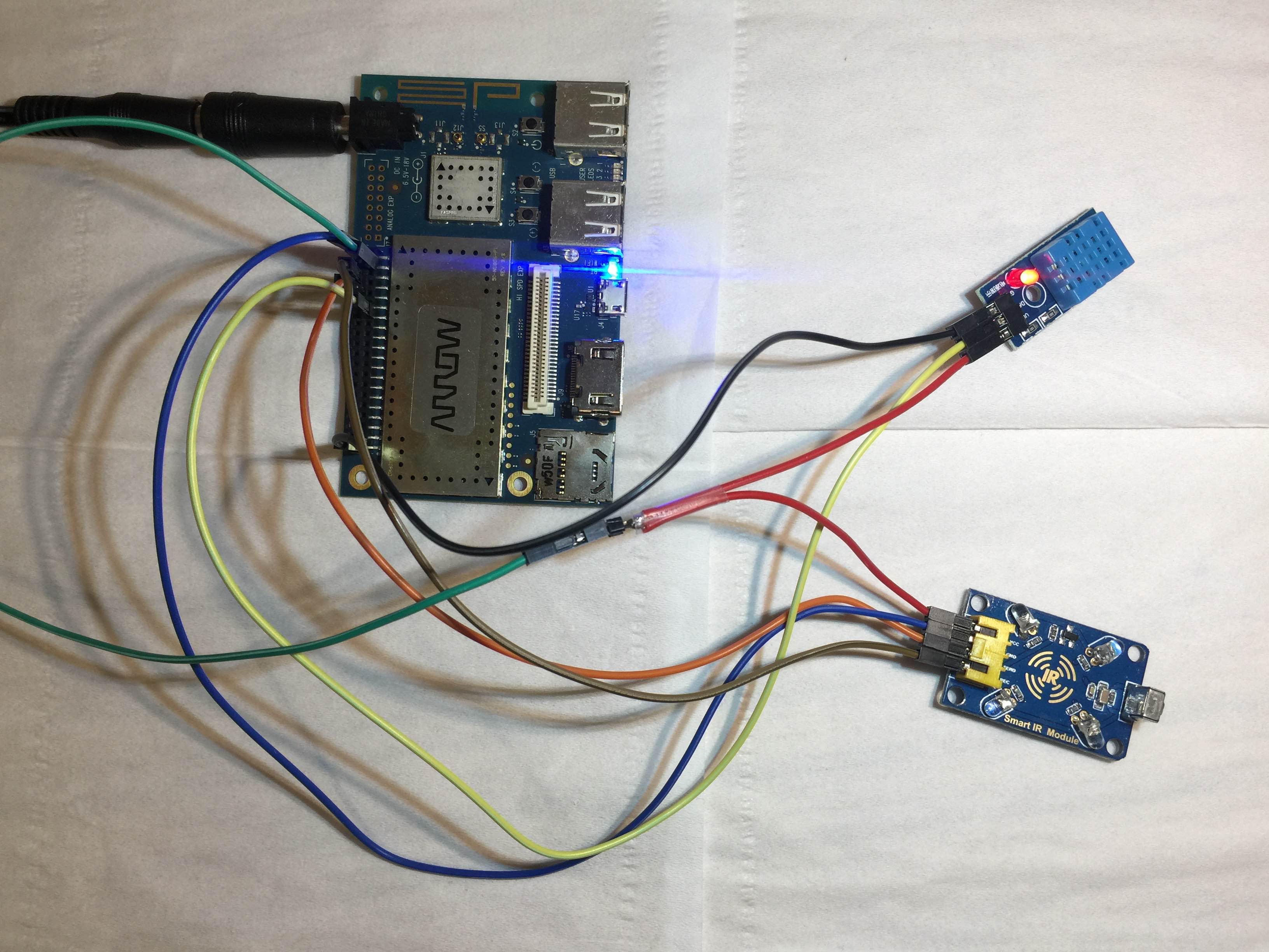


关于红外遥控
本来在等待龙板到手的这段时间里,已经在树莓派上把LIRC遥控空调跑通了,并且录制了空调的红外码,不过试用时间只够调整完DHT11驱动的,LIRC的驱动踩了很多坑需要调整lirc_dev和lirc_rpi(用树莓派的改写)两个驱动,所以目前还没有改写完- -!
你这更新的有点慢哈,没事多发点